Seismic Experiment for Interior Structure (SEIS)
mission specific
Description
The purpose of the SEIS instrument is to measure the surface ground velocity by a set of seismometers covering the 0.01-10 Hz frequency bandwidth for the 3 axis Very Broad Band (VBB) sensors and 0.1-50 Hz for the 3 axis Short Period (SP) sensors. These measurements are augmented by a gravity output of the VBBs (down to 50 mHz, the Phobos tide frequency), an overlap of the VBB and SP seismic sensors bandwidth outside their nominal bandwidth and by additional measurements enabling a better characterization and possibly mitigation of the lander and atmospheric generated noises.
The SEIS sensors will be deployed on the Mars surface by a robotic arm and will then operate almost continuously until end of mission. In summary, the instrument consists of the following functional subunits:
- SEIS Acquisition and Control Electronics(SEIS -AC), located in the lander warm electronics box
- Sensor Assembly (SA) (including the Leveling System (LVL), the VBBs, the SPs, a set of temperature and tilt sensors and the Thermal Blanket (TBK). The SA will be deployed onto the surface.
- SEIS Tether system, which connects the SEIS-AC and the SA and is made of a tether, a tether box, and of a service loop and associated release shunt.
- A SEIS cradle, staying on the lander and locking the SA prior its deployment to the lander
- A Wind and Thermal Shield (WTS), deployed over the SA and providing thermal and wind protection.
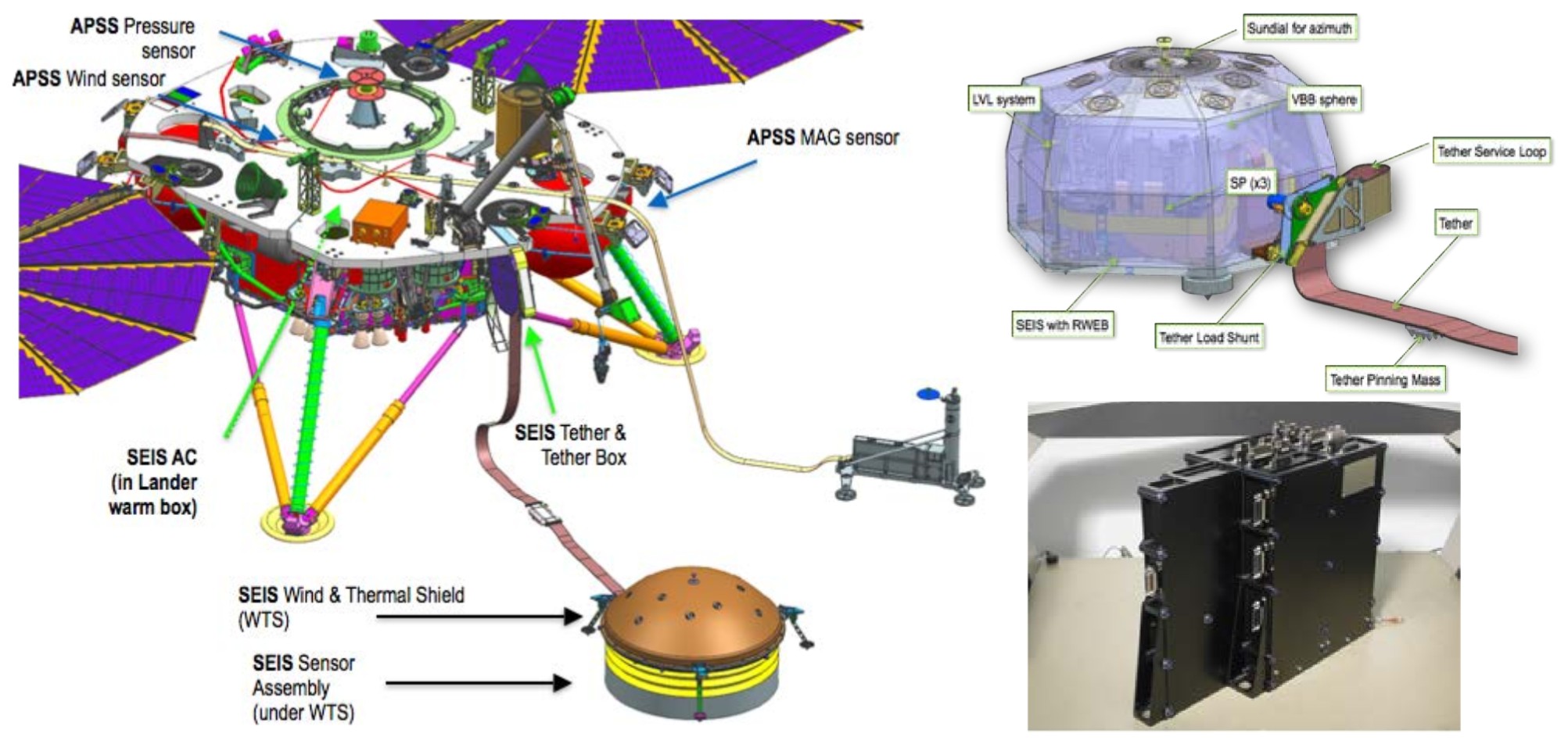
Different subsystems of the SEIS experiment when deployed on the ground by the robotic arm. On the left, the WTS covering the Sensor assembly (1a). On the Right: top (1b), Sensor Assembly (SA) and bottom (1c), SEIS acquisition and control electronics (SEIS-AC)
In addition, SEIS will be supported by the Auxiliary Payload Support System (APSS), which will provide additional measurements of the magnetic field using the 3-axis InSight Flux Gate (IFG) magnetometer, of the pressure field with a micro barometer sensor, and Temperature and Winds for InSight (TWINS) sensors.
A functional block diagram of the instrument is shown in the figure below where the different subsystems are indicated by colors. The three VBB axes are fully independent one from each other while the 3 SPs share a common feedback card. All feedback cards are located in the lander SEIS-AC and will therefore have their temperature controlled by the lander warm box. Note that the SEIS-AC is fully redundant. The LVL control electronics is not redundant, but the three legs of the Leveling Platform are motorized while only two are needed to achieve the VBBs leveling with a resolution better than 0.1°.
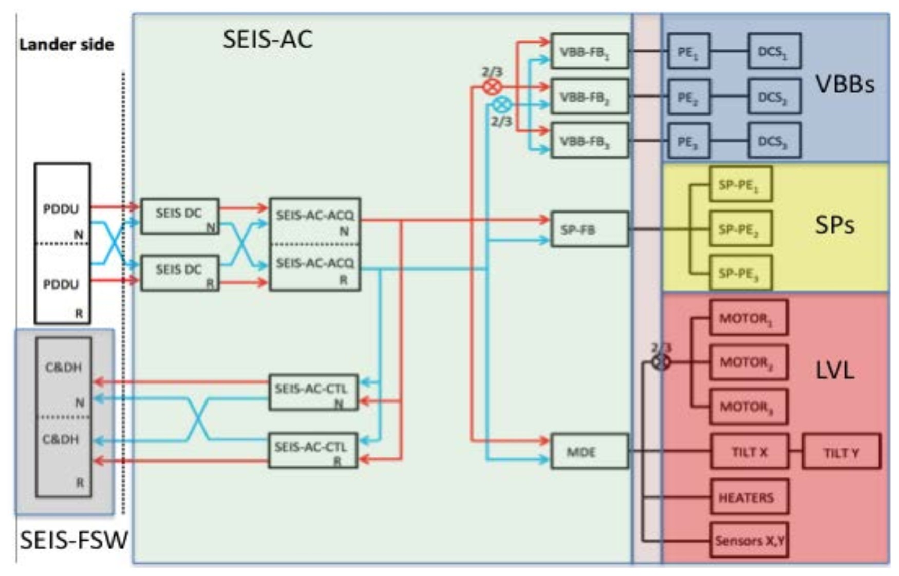
Functional block diagram of the SEIS instrument indicating the lander mounted SEIS-AC, the tether connecting the SEIS-AC to the deployed element and the subsystems of the Sensor Assembly, including the 3 VBBs, the three SPs and the motors and two different tiltmeters of the LVL (coarse tiltmeter for platform leveling and fine tiltmeters for precise calibration). Several temperature sensors are complementing the block diagram and monitor the various boards of SEIS-AC, Sensors heads and sensor proximity electronics (PE) plus a scientific temperature sensor located on the ring of the LVL structure. Not indicated in the block diagram as disconnected electrically from SEIS are the Wind and Thermal Shield (WTS), and the cradle supporting the SA during launch, cruise, and entry, descent, and landing.
Science Objectives
Threshold Science Objectives
Eight out of the ten Level 1 requirements of the InSight mission are associated with the SEIS science objectives. These are listed in the table below together with references illustrating possible data processing techniques that have been used or proposed for seismological studies of Mars or the Moon. Many other techniques have of course been developed for Earth, but are typically used for seismic network data processing.
Both structure and activity related science data products will be integrated into a structure model catalogue and an activity catalogue, which will be delivered by the SEIS team at the end of the nominal mission.
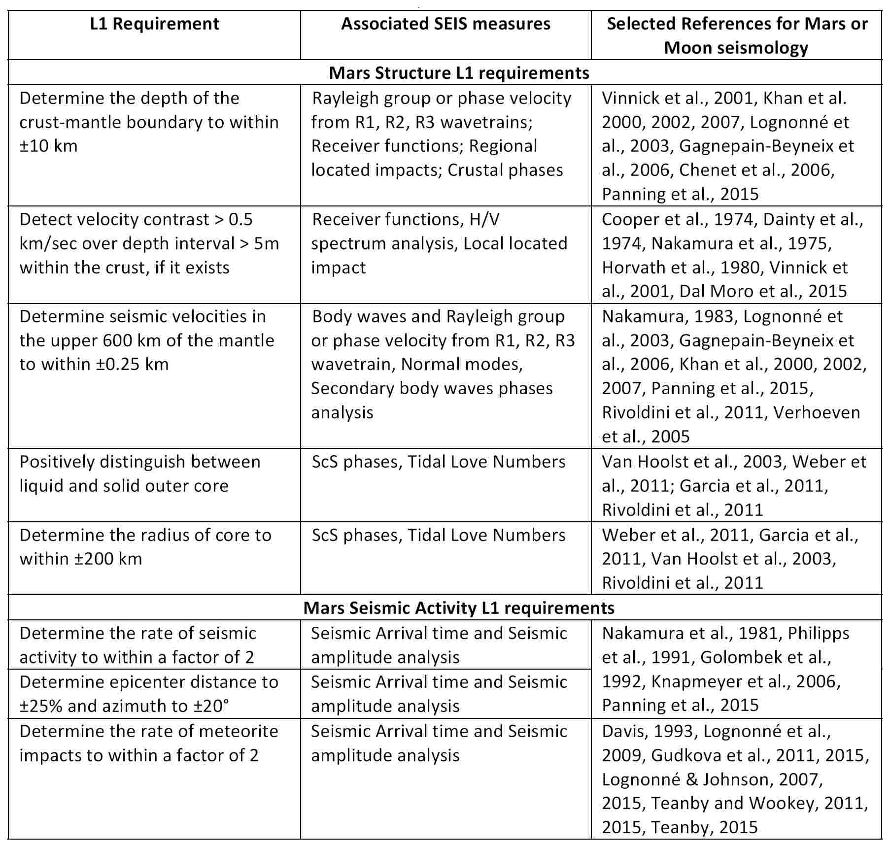
Threshold (Structure related) and baseline (Activity related) science goals of the SEIS Experiment
Science Goal Implementation and Sensor Performances
Sensor Performances
With only one lander and an expected relatively low Mars seismic activity, the InSight SEIS requires a low instrument noise level (10-9 ms-2/Hz1/2 in the bandwidth 0.01 to 1 Hz and 10-8 ms-2/Hz1/2 in the bandwidth 1 Hz- 10 Hz). The performance and installation quality of the InSight seismometer will therefore be critical parameters to ensure success with a sensitivity higher than previous Mars seismometers (see Anderson et al., 1977 and Lognonné et al., 1998). SEIS also can expect a much better deployment because of the robotic installation of SEIS from the deck of the lander down to the ground followed by the lowering of a wind and thermal shield (WTS) on the SA. Figure 4.1.3.1-1 illustrates the packaging and configurations of the VBBs, including the evacuated titanium sphere in which VBB sensors are located. A thermal blanket is wrapped around both the VBB sphere and SPs and the WTS will provide additional shielding. All together, these three thermal barriers produce an effective two level thermal filter with time constants of 2 hr and 5.5 hr. It is likely that SEIS will be close to the best deployment and sensitivity that can be achieved by a robotic installation on the surface of Mars.
The SEIS VBB (see first figure below) is based around three inverted oblique pendulums, with gravity acting against the spring to lower the pendulum natural frequency to about 0.45Hz for a proof mass of 190 g. It uses a highly sensitive capacitive transducer to drive a feedback designed to provide a response that is relatively flat in ground velocity to within 10 dB from 50 to 0.5 s, with an expected noise below 10-9m s-2 Hz-1/2 between 0.02 and 2 Hz on the vertical (VEL) output. The output is digitized at 24 bits, giving 10 dB headroom over the instrument noise floor and a saturation threshold larger than Viking. The VBB has in addition a thermal compensation mechanism, which will be tuned on Mars in order to minimize the amplitudes of thermally driven daily variations, enabling in addition to the VEL output the records of a High Gain Mass position output (POS), flat in ground acceleration from DC to 0.02 Hz and with expected self noise of 10-9 m s-2 Hz-1/2 between 0.005 and 0.02 Hz. All VBB are located in a titanium sphere, which maintains low pressure until end of mission and minimizes the proof mass Brownian noise to <3 x 10⁻¹⁰ m s-2 Hz-1/2. Expected sensor self noise and gains in the range of operating conditions are given in the second figure below . Axes in the X, Y, and Z directions are made through recomposition of the three oblique axes.
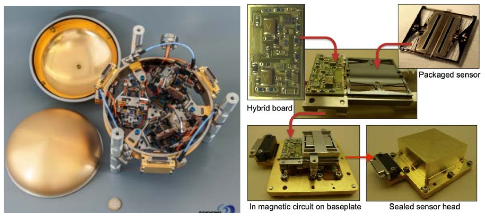
(Left) Flight Sphere with the 3 VBBs before sphere closure. (Right) SP QM sensor and its integration scheme in the SP sealed sensor head.
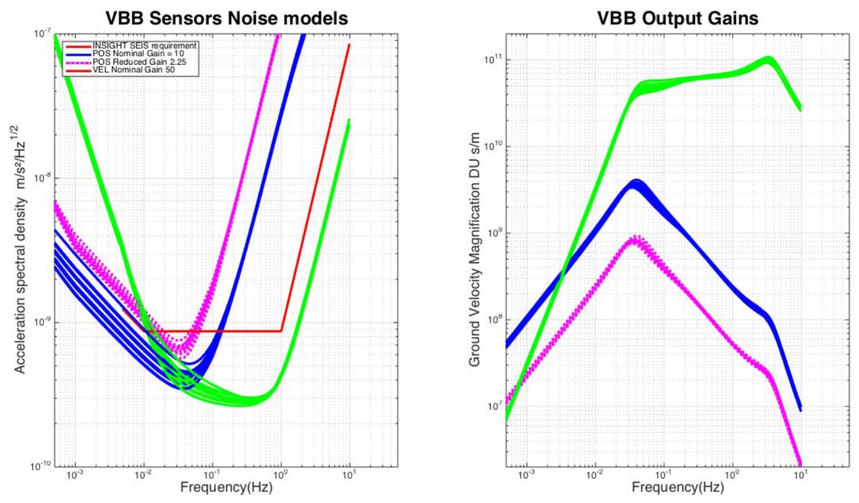
Noise models and gains (in Digital Unit (DU) per ground velocity (m/s), e.g. DU s/m) of the 3 flight model VBB sensors, for temperature between -65° and -25°C (corresponding to typical temperature seasonal variations). Nominal velocity and position outputs are the green and blue lines, respectively, while the reduced Gain gravity outputs (POS) are the magenta ones. Red line is the InSight SEIS Vertical requirement projected at the sensor level (Z noise is amplified by about 1.15 while the horizontal noise is reduced by about 0.77, as compared to the oblique VBB noise).
SEIS SP consists of a set of micromachined sensor heads, one vertical and two horizontal axes. The suspension and proof mass of each sensor are etched from single-crystal silicon wafers using deep reactive ion etching to produce a 6 Hz suspension and a 0.5 g proof mass. The motion of the proof mass is capacitively measured by the change in overlap between an array of electrodes on the proof mass and an opposed fixed array connected to the outer frame of the suspension. A sliding rather than squeeze-film gas damping occurs in the capacitive transducer, a Q of a few hundred can be achieved without evacuation. SEIS SP’s feedback produces a flat velocity output over a bandwidth from 40 Hz after anti-alias finite impulse response (FIR) to below 0.05 Hz producing an overlap with the VBB, with a determined acceleration sensitivity of 5 x 10⁻⁹ ms-2 Hz-1/2. The sensor self noise as determined on Earth and gains in the range of operating conditions are given in the figure below.
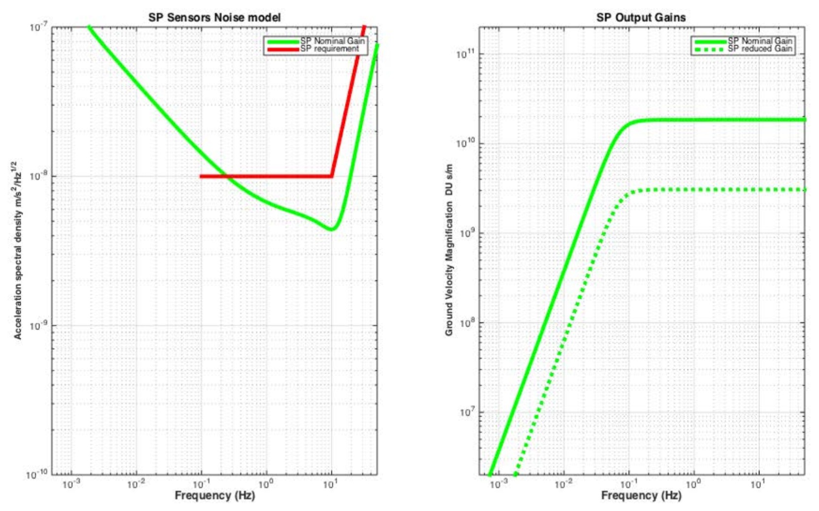
Noise models and Gain (in DU s/m) of the flight model SPs. Nominal Velocity Gain and reduced Velocity Gain are the green and blue lines, respectively. Red line is the InSight SEIS Vertical requirement.
Installation and A Priori Seismic Noise
It is expected that environmental noise will, especially during the day, be the first source of noise. Part of this noise is associated with temperature variations, partially filtered by the SEIS thermal protection and is related to the surface installation. Typical diurnal temperature variations are however expected to be ~10°C in winter and ~22°C in summer at the VBBs sensor locations with larger temperature variations on the LVL and SPs. Another noise contribution is related to the a priori low rigidity of the Martian upper subsurface, which leads to ground deformations/vibrations generated by pressure fluctuations of the atmosphere or the interaction of the lander and of the WTS with the wind flow. Although considerably smaller than those reported by the Viking experiment (Anderson et al., 1977, Nakamura and Anderson, 1979, Lorenz, 2012), diurnal noise variations will likely be observed in the range of 10-9 ms-2 Hz-1/2 to 10-8ms-2 Hz-1/2 (see the figure below, a and b, for the day and night micro-seismic noise prediction of the SEIS noise model). In the short period range, a larger noise is expected to be associated with the lander solar panels and structural wind-excited oscillations (figure below, c). Although part of this noise is expected to be decorrelated by the APSS sensors, the non-seismic origin of that part of the recorded noise will have to be integrated in all noise analysis.
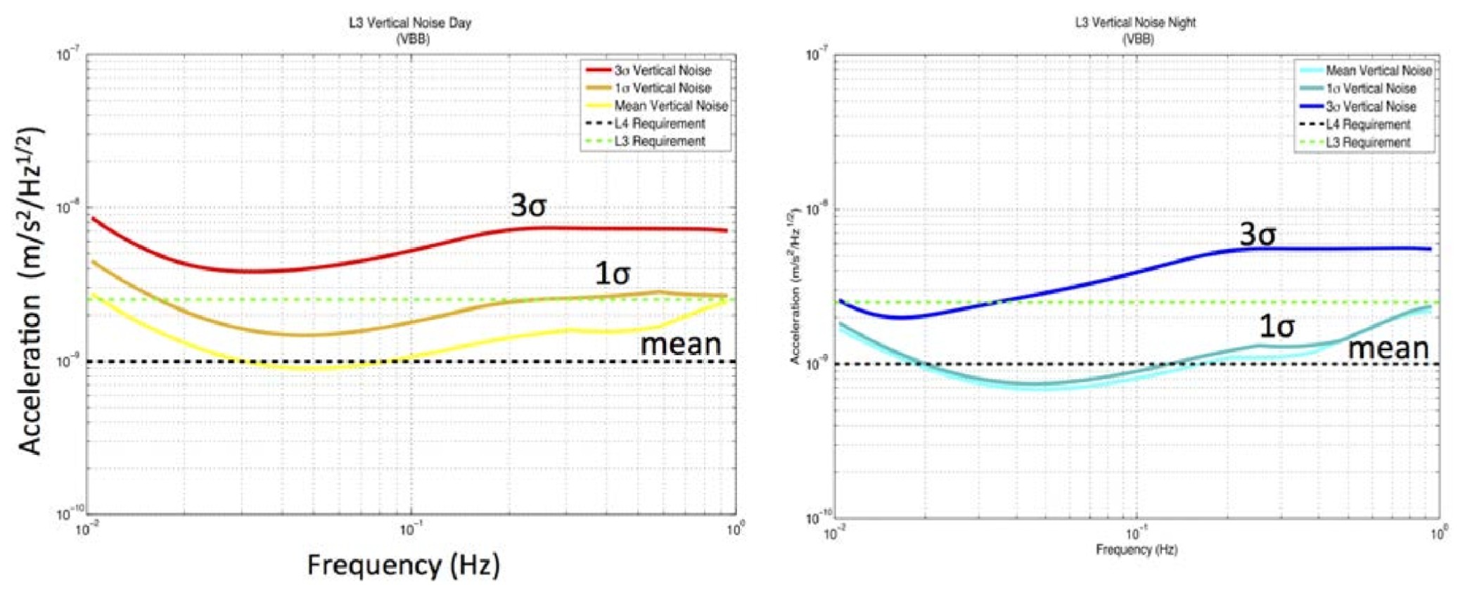

(a) Top right. Noise model in the VBB bandwidth and on the vertical component during the day. σ is defined as the 70% fraction of the SEIS operation. This noise integrates the thermal noise and the noise from ground deformation induced by pressure fluctuation. (b) Same but during night. (c) Model of the high frequency lander generated noise. Solid curves are for the noise generated through elastic deformation of the ground, as predicted by an analytical model, while dashed curves are for the noise from a dynamic model integrating the structural resonances of the lander solar panels. Blue, Green and Red are for the X, Y and Z components, respectively.
SEIS Auxiliary Sensors
A set of temperature sensors will monitor the temperatures of the subsystems, including all VBB sensors (16 bits 2 wires PT1000, 1/10 sps, 1/100K resolution), the LVL ring system with a SCIentific Temperature (SCIT, 24 bits 4 wires PT1000, 1/200K resolution) and sensor Proximity Electronics (PEs) and Feedback (FB) cards (12 bits 2 wires PT100, 1/10 sps, 1/10 resolution). Accuracy of the SCI Temperature is better than 0.25 K while others are about 1 K.
The LVL is equipped with two types of tiltmeter, each type recording the two axis tilts of the LVL ring coordinate common to the VBB horizontal plane. The first one is a coarse MEMS type tiltmeter while the second one is an electrolytic precise tiltmeter. Both are acquired by a 12 bit analog-to-digital converter (ADC), with an oversampling ratio defined by command. Measured resolution of the flight model MEMS and Electrolitics Tilmeters are around 140 arcsec and < 0.7 arcsec, respectively.
SEIS Acquisition Performance
All SEIS high rate seismic data (VBB VEL and SP) are sampled by a dedicated 24 bit ADC at a primary rate of 500 sps and then decimated by FIRs down to the selected output rate (100 sps or 20 sps). Low rate science data (VBB POS, SCI Temperature) are sampled by a dedicated 24 bit ADC at a primary rate of 10 sps. VBB temperatures have also a primary sampling of 10 sps but with a 16 bit ADC. These low rate data are then decimated by FIRs down to the selected output rate (1 sps or 1/10 sps). All FIRs can be remotely updated and are designed with 120 dB attenuation above the Nyquist and less than 3 dB of attenuation at frequencies below 80% of the Nyquist. Other House Keeping data, as briefly described in the Appendix A, are sampled at the selected rate (typically 1/100 sps for nominal conditions).
Instrument Operation
SEIS Operations
After deployment of the instrument onto the surface of Mars by the InSight robotic arm, operations of the SEIS instrument are expected to be continuous, with the exception of severe lander power restriction or emergencies. This continuous operation is made possible by the autonomy of the SEIS-AC, which enables the SEIS operation even when the lander is in sleeping mode. Change in SEIS operation modes as well as calibrations and LVL activations are possible only when the lander is awake.
All data will be stored in the SEIS-AC mass memory before being transmitted to the lander mass memory during lander wake-ups. Similarly, APSS data will also be sampled at high rate (20 sps for pressure and 3 axis magnetic field and 1 sps for the wind). Both SEIS and APSS data will generate about 600 Mbits/sol, too high a volume for full transmission. The data are therefore decimated in order to fit in the SEIS data transmission allocation of 30 Mbits/sol. See SEIS Flight Software Operation below for details on the decimation and generation of the continuous data flow.
Continuous data will be sent regularly to Earth and processed by the SEIS operation center, SISMOC, located at the Technical Center of the French Space Agency CNES in Toulouse (France). These data will then be processed in order to identify the occurrence of quakes, and event requests will be made to recover the high frequency SP, VBB and when necessary APSS data corresponding to the event period. About 5 Mbits per sol of SEIS event data are planned on average, corresponding to about 15 minutes of SP raw data at 100 sps and 10 mins of VBB raw data at 10 sps, as well as the high rate APSS data of the same periods. 3 additional Mbits per sol are allocated to APSS only events.
Calibration
VBB VEL and SP Calibrations
Calibration of the VBB VEL and SP outputs will be performed through built-in calibration coil and digital to analogue generator, calibrating all individual axes. Calibration of these seismic outputs is better than 5% and the calibration signal can be remotely uploaded if requested. Pre-launch calibration of the flight model VBB has been performed at several temperatures within the operating range for better knowledge of the temperature variations of the transfer function and calibration coil efficiency. These calibration data will be used for resolving the 3 axis ground acceleration into X, Y, and Z components. The LVL resonances have also been calibrated and mainly affect the horizontal components. The resonances are in the range of 30- 50 Hz with a structural resonance quality Q<10 on the Z component depending on the length of the LVL feet and deployment geometry.
VBB POS Calibrations
Additional calibration of the VBB POS output will be performed on Mars during SEIS commissioning and one sol every month in order to achieve the gravity measurement accuracy requested for tidal analysis. These calibrations will be performed by a series of LVL tilts measured by the electrolytic tiltmeter and used as calibration tilts for the VBBs, in addition to VBB open loop frequency measurements. The calibration goal is to reach in-situ accuracy of 0.2% within 0.1° of LVL tilt.
VBB and SP Environment Sensitivity Calibration
APSS sensors will be used to perform on-site decorrelation of pressure and magnetic field sensitivity. Pressure noise will be mainly related to ground deformation driven by the wind supported pressure fluctuations (Sorrels, 1971, Zürn and Widmer, 1995, Beauduin et al., 1996), while magnetic field is expected to affect the VBB sensor (Forbriger et al., 2010) as the later has no mu-metal shielding. Performances of the APSS sensors are described below.
SEIS Flight Software Operation
In addition to the Instrument operation, the SEIS flight software (SEIS FSW) will play a key role in the on board management of the science data. SEIS FSW will:
- store the raw data acquired at high sampling rate (i.e. 100 sps for SPs , 20 sps for VBBs, APSS Pressure and APSS IFG, 1 sps for APSS TWINS) in the lander mass memory. These data will remains in the lander mass memory for about 6 weeks, depending on the compression of data.
- generate from these data a flow of continuous data adjusted to the SEIS transmission allocation bandwidth. For nominal bandwidth, this is made by down sampling the 3 axis VBB data into three 2 sps continuous time series and by the production of a single 10 sps, vertical like time series from summation of and hybridization of both VBBs and SPs channels (SEISVELZ). Similar decimations are made from the APSS data and in addition, the average high passed seismic energy of the Vertical SP is sent every second (ESTASP) together with the similar high frequency energy of the pressure (ESTAP) and magnetometer (ESTAM). These continuous data are summarized in the table below together with those of the APSS sensors for SEIS support and will make a total of about 30 Mbits per sol
- extract and when requested decimate the event data down to the selected output rate (e.g. 100, 50 or 25 sps for SPs, 20 or 10 sps for VBBs)
- perform sensor replacement in case of any sensor failure. This might be done by generating a replacement 20 sps time series from the 100 sps SPs (in case of one VBB failure), or by decimating the replacement 100 sps VBBs to nominal 20 sps (in case of SP failure).
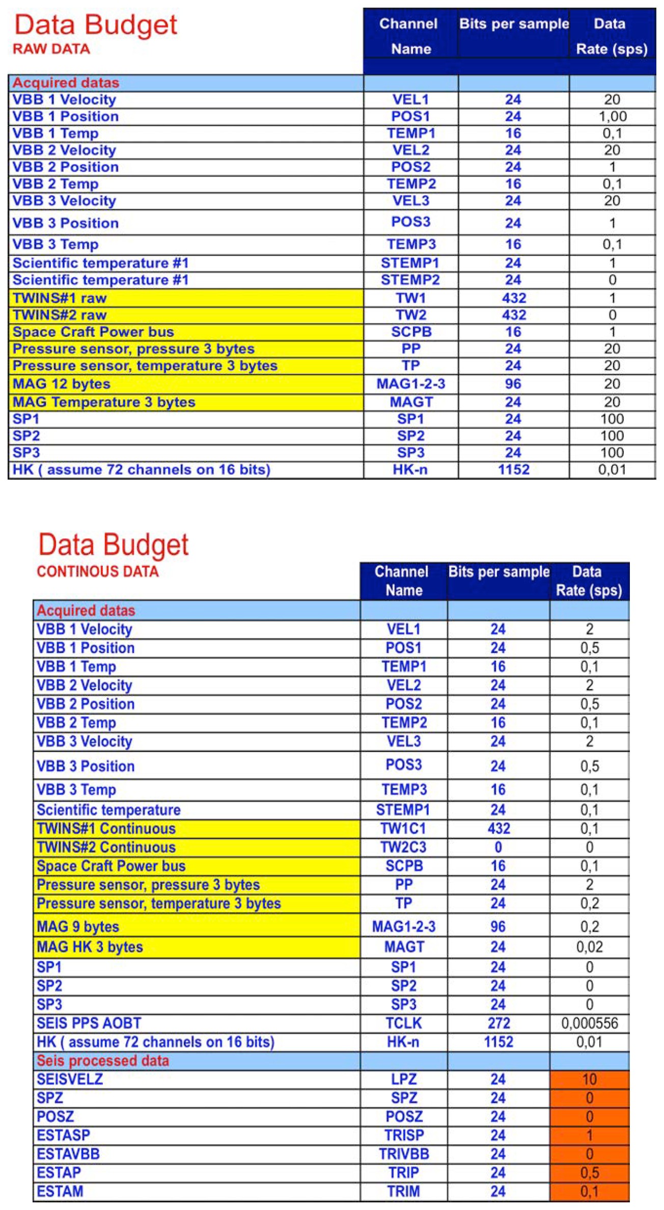
List of the continuous data transmitted to Earth. All data will be decimated by FIRs and further processed for the ESTA signals, which correspond to the average variance of the high pass filtered signals. See more details in the mission Data Archiving Plan.
Ground System Operation
The figure below summarizes the ground operations of SEIS, including Project and Science Tactical and Science Non-tactical activities.

SEIS ground system structure, including the Tactical Operation at SISMOC, Science Tactical and non-Tactical operations and Science team and outreach activities. CAB, UCLA, and Cornell are part of the APSS instruments.
Project tactical activities will be performed by the SEIS Operation Center (SISMOC) center at CNES, which will be responsible for the SEIS operation and the generation of the SEIS data in mini-SEED data (SEED is for Standard for the Exchange of Earthquake Data, see Ahern et al., 2012 and Appendix A for a description of SEED and mini-SEED data). Data will then be distributed in SEED by the IPGP Data center (https://datacenter.ipgp.fr ) and the hosted SEIS data service (in development at this time, https://www.seis-insight.eu/fr ). This SEIS data service will distribute both the proprietary SEIS data to the SEIS team and, together with IRIS Data Management Center and NASA Planetary Data System, the non-proprietary data after the PDS release dates.
SEIS and APSS science tactical activities will mainly consist of the fast analysis (one week cycle) of the continuous data in order to identify seismic events, to perform first analysis of these events (arrival times, pre-location, etc.) and to format event requests for the downlink of the associated high rate data. This task will be coordinated by the Mars Quake Service, hosted by the Swiss Federal Institute of Technology in Zurich (ETHZ, Zürich, Switzerland) together with the Institut Supérieur de l’Aéronautique et de l’Espace (ISAE, Toulouse/France) and the Jet Propulsion Laboratory (JPL, Pasadena, USA). Event requests may be made by all team members. Data prioritization will be made weekly at the SEIS-InSight project level. The Mars Structure Service will coordinate research activities associated with the generation of internal models of Mars (and associated Mars Structure catalogue) and will be hosted by the Institut de Physique du Globe de Paris (IPGP) together with University of Florida and University of Nantes.
Educational activities will also be performed through the transmission of the data to a network of several hundred of middle and high schools worldwide, associated with several "seismo at school" programs in the United States (https://www.iris.edu/hq/sis ), France (https://www.edusismo.org [page no longer functioning]), Switzerland (http://www.seismo.ethz.ch/ ) and the United Kingdom (http://www.bgs.ac.uk/schoolseismology [page no longer functioning]).
SEIS data in SEED format
The SEIS data archived in PDS are also available in SEED format through the Incorporated Research Institutions for Seismology (IRIS) and through the Institut de Physique du Globe de Paris (IPGP).